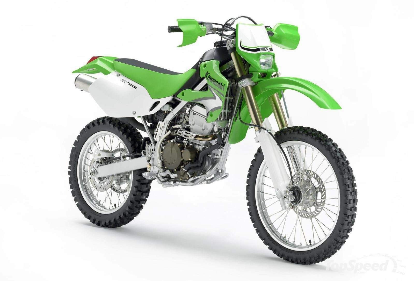
Klx 300 Engine Manual
The Float The float bowl acts as a fuel reservoir to meet engine demand. The float is hinged on a pin in the float boss. It rises and falls with the fuel level in the float bowl. The small metal tang integrated in the plastic float supports the float valve, also known as the float needle. As the fuel in the float bowl rises, the float valve is pushed into the valve seat, until it’s high enough to shut off the fuel flow to the bowl. As fuel is used the level in the bowl drops lowering the float which pulls the float valve from its seat, and fills again.
2003 KLX 300 engine making strange ticking sound. **FIXED**: replaced the automatic cam chain tensioner with a manual Krieger one. Mods: -fmf powercore4 pip. Feb 24, 2008 - KLX 250S - KLX250 KLX300 Service Manual - OK, good news guys and girls. Just finished running the manuals through my OCR program for. Kawasaki KLX 250/300 Dual Sport Kit. Installation Manual. Locate the AC voltage regulator found mounted to the frame just behind the engine on the left.

Adjusting the height of the float has a big effect on the mixture as a low or high float level makes it harder or easier for the vacuum to suck fuel into the venturi. Differing float levels cause an imbalance which may be perceived as vibration. The Choke This system is referred to as the choke.
But that’s a misnomer. When you pull the choke knob, what you’re doing is retracting a plunger that opens a tube connected to the starter jet, allowing additional fuel to enter the venturi just below the vacuum hose nipple. It supplements the pilot system at start up. The Pilot System The primary purpose of the pilot system is to supply the mixture at idle. It continues to supply fuel throughout the entire throttle range, but after about 1/8 throttle is reached the main system starts to put out more of the total mixture, up to full throttle. By adjusting the idle with the big screw on the left side of the carburettors the position of the butterfly is altered, so exposing one or more of the four small holes that are drilled into the venturi, (leading to the pilot jet) just under the butterfly valve, letting more or less air pass the butterfly.
Adjusting the pilot screw that’s under the carburettor varies the amount of air premixing with the fuel before it enters the venturi. The Main System Open the throttle and the cable that’s connected to the butterfly valve turns it from vertical to horizontal, so letting more air through the venturi. This increases the vacuum effect that is transferred up through the vacuum drilling in the slide to the diaphragm valve that leads to the diaphragm chamber. The top chamber is separated from the bottom by a rubber diaphragm.
The bottom chamber is open to atmospheric pressure from the airbox. When the vacuum in the top chamber rises enough, the constant ambient pressure of the lower chamber helps the diaphragm valve overcome the downward force of the diaphragm spring, so it rises from the ven- turi. As the diaphragm is raised the needle is pulled out of the needle jet, exposing a thinner portion of the needle taper which allows more fuel to rise into the venturi to meet the increased engine demand. The key parts of the main system are shown in the photo below Incoming search terms:. Repair manual KTM 250 / 300 / 380 Art No 3206004 -E 2-2C main jet jet needle jet needle air control screw idle adjusting screw idle jet throttle valve Idling range A Operation with closed throttle valve. This range is influenced by the position of the air control screw 1 and the idle adjusting screw 2. Only make adjustments when the engine is hot.
To this end, slightly increase the idling speed of the engine by means of the idle adjusting screw. Turning it clockwise produces a higher idling speed and turning the screw counterclockwise produces a lower idling speed. Create a round and stable engine speed using the air control screw (basic position of the air control screw = open by 1.5 turns). Then adjust to the normal idling speed by means of the idle adjusting screw. Opening up B Engine behavior when the throttle opens. The idle jet and the shape of the throttle valve influences this range.
If, despite good idling-speed and part-throttle setting, the engine sputters and smokes when the throttle is fully opened and develops its full power not smoothly but suddenly at high engine speeds, the mixture to the carburetor will be too rich, the fuel level too high or the float needle is leaking. Part-throttle range C Operation with partly open throttle valve. This range is only influenced by the jet needle (shape and position). The optimum part-throttle setting is controlled by the idling setting in the lower range and by the main jet in the upper range. If the engine runs on a four-stroke cycle or with reduced power when it is accelerated with the throttle partly open, the jet needle must be lowered by one notch. If then the engine pings, especially when accelerating under full power at maximum engine revs, the jet needle should be raised.
If these faults should occur at the lower end of the part throttle range at a four-stroke running, make the idling range leaner; if the engine pings, adjust the idling range richer. Full throttle range D Operation with the throttle fully open (flat out).
This range is influenced by the main jet and the jet needle. If the porcelain of the new spark plug is found to have a very bright or white coating or if the engine rings, after a short distance of riding flat out, a larger main jet is required. If the porcelain is dark brown or black with soot the main jet must be replaced by a smaller one. Mixture too rich: too much fuel in proportion to air mixture too lean: not enough fuel in proportion to air 1 2 OPERATING RANGES OF THE CARBURETOR 2-3C Carburetor adjustment Basic information on the original carburetor setting The original carburetor setting was adapted for an altitude of approx.

500 meters (1600 ft.) above sea level, and the ambient temperature of approx. 20°C (68°F), mainly for off-road use and central European premium-grade fuel (ROZ 95 MOZ). Mixing ratio 2-stroke motor oil: super fuel 1:40 – 1:60. Basic information on a change of the carburetor setting Always start out from the original carburetor setting. Essential requirements are a clean air filter system, air-tight exhaust system and an intact carburetor. Experience has shown that adjusting the main jet, the idling jet and the jet needle is sufficient and that changes of other parts of the carburetor will not greatly affect engine performance. RULE OF THUMB: Incoming search terms:.
ATV Carburetor Repair Kits Complete kits to rebuild one OEM carburetor. Each kit contains necessary gaskets/o-rings, needle valve or needle valve set, and jets.
Made in Japan. Note: Check all parts before installation. Engine assembly requires special attention to detail. Your cylinder must be bored to fit this new piston. For long engine life it is very important that the cylinder bore is professionally machined to be very round and without taper. Piston-to-Cylinder Clearance:.002″ Ring End Gap:.007″ –.012″ Once the cylinder is bored to size, installation of this piston kit is identical to OEM installation.
Please refer to the Kawasaki shop manual or a qualified mechanic for assistance.The side of the piston marked EX should go toward the exhaust port. Coat both sides of copper gasket with a quality gasket sealer. (Gasgacinch or comparable product) Every effort has been made to insure the quality of this product.
Because BBR cannot control the installation or use there is NO warranty or guarantee with this product. Using quality motorcycle oil will help prolong engine life.
Be sure to change it often. Recommended main jet: 100 Main (at sea level, 65 degrees) Recommended Fuel: 91-93 octane pump fuel.
Remove the plug bolt from the back of the cam chain tensioner assembly. It is under pressure from the spring.
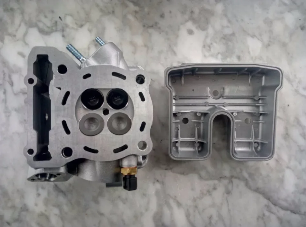
Remove the spring and pin. Remove the bolts and tensioner assembly from the cylinder. Release the lock on the tensioner assembly and push the tensioner rod into the assembly so that it is fully retracted. Remove the eight 5mm Allen headed bolts that hold the cam caps in place. Remove the cam caps; be aware of the locating dowels in the caps to keep them from falling into the engine.
It may be necessary to pry very lightly on the caps to lift them off their dowel pins. Do not use the cam lobe as the pry point. Lift the intake camshaft out of its pocket in the cylinder head casting. Remove the cam chain from the sprocket, set the stock camshaft aside. Lift the exhaust cam out of its pocket in the cylinder head casting and remove the chain from the sprocket. Do not drop the cam chain; dangle it over the side of the engine while keeping slight upward pressure on the chain to maintain its position on the drive sprocket on the crankshaft.
Using assembly lube, lube the shim buckets and bearing surfaces for the camshafts in the cylinder head. Set the exhaust camshaft into the cylinder head casting while at the same time fitting the cam chain over the sprocket. Make sure that you keep all the cam chain slack to the back of the engine. Repeat the above process for the intake camshaft. Again, make sure you keep the chain slack to the cam chain tensioner side of the engine. Check to be sure the crankshaft is still at TDC. Check the location of the cam lobes.
Ford 300 Engine
The camshafts are marked, and preset to 108-degree centers. If the lobes are not where they should be, adjust the positioning of the camshaft by rotating the sprocket one tooth on the chain. Do this until it is in the correct position as before you removed the camshafts.
Check the positioning of the crankshaft for the TDC mark. Short circuit button (SX) The short circuit button 1 turns off the engine. When pressing this button, the ignition circuit is short-circuited.

Combination switch (EXC) The light switch has 2, respectively 3 switch positions. A = Light off (this function is not available in all models) B = Low beam on C = High beam on You may use button 2 to actuate the horn.
The red short circuit button 3 serves to switch off the engine. Leave the switch pressed until the engine stops. Headlamp switch (XC-W) In this model the headlamp is switched on with the pull switch 4. Flasher switch The flasher switch is a separate unit and is mounted on the left portion of the handlebar.
The wire harness is designed in a way that whenever you want to use your bike off-road, you can dismount the entire turn indicator system without affecting the function of the remaining electrical system. Flasher left Flasher right Emergency OFF switch (Australia) The emergency OFF switch 5 is located next to the throttle grip.
Primarily designed as safety or emergency OFF switch, it should normally not be in its activated state. In this position, the ignition circuit is shorted; if the engine is running, it will stall immediately, if it is at standstill, it will not start. In this position, the ignition circuit is enabled; the engine should start. 1 2 3 5 A B C 4 ENGLISH 12 Filler cap To open it: turn filler cap counter-clockwise. To close it: put filler cap back on and tighten it by turning it clockwise.
Kawasaki Klx 300 Workshop Manual
Install tank breather hose 1 without kinks. Filler cap (XC, XC-W) To open the filler cap: Turn the filler cap 45 ° counter-clockwise. To close the filler cap: Put the filler cap on and turn it 45 ° clockwise. Fuel tap OFF In this position the fuel tap is closed. No fuel can flow to the carbure- tor. ON During operation the twist grip must be turned to ON.
This means that the fuel can flow to the carburetor. With the twist grip in this position the tank will be emptied until only the reserve is left. RES The reserve tank cannot be tapped until the rotating handle is turned to the RES position. Fill the tank as soon as possible and remember to turn the rotating handle back to the ON position so that you will have backup fuel next time, too. Reserve of the 8.5 l tank. 1.3 l (0.32 USgallons) Reserve of the 10 l tank.1.7 l (0.45 USgallons.
Compression damping of shock absorber (MXC, EXC) The compression damping (during compression) can be adjusted for the MXC and EXC shock absorbers (Mono Compression Control). The degree of damping can be adjusted by turning adjusting screw 1 with a screwdriver. Turning in a clockwise direction will increase the damping, turning in a counterclockwise direction will decrease the damping. STANDARD ADJUSTMENT: -Turn the adjusting screw clockwise to the stop.Then turn the adjusting screw counterclockwise, counting the number of clicks that corresponds to the respective type of shock absorber. Type White Power 1218X757.17 clicks Type White Power 1218X759.17 clicks.
WARNING. THE DAMPING UNIT OF THE SHOCK ABSORBER IS FILLED WITH HIGH – COMPRESSION NITROGEN. NEVER TRY TO TAKE THE SHOCK ABSORBER APART OR TO DO ANY MAINTEN – ANCE WORK YOURSELF. SEVERE INJURIES COULD BE THE RESULT.
NEVER UNSCREW THE BLACK SCREW 2 CONNECTION (24 MM ). Rebound damping of shock absorber (SX, MXC, EXC) By using the adjusting screw 3, the degree of damping of the rebound can be adjusted. Turn the knob to the right side to increase damping, turn it to the left side to reduce damping during rebounding.
STANDARD ADJUSTMENT: -Turn the adjusting screw clockwise to the stop.Then turn the adjusting screw counterclockwise, counting the number of clicks that corresponds to the respective type of shock absorber. Type White Power 1218X756.28 clicks Type White Power 1218X757.28 clicks Type White Power 1218X759.26 clicks.
Chrysler 300 Engine
WARNING. THE DAMPING UNIT OF THE SHOCK ABSORBER IS FILLED WITH HIGH – COMPRESSION NITROGEN. N EVERTRYTOTAKETHESHOCKABSORBERAPARTORTODOANYMAINTE – NANCE WORK YOURSELF. SEVERE INJURIES COULD BE THE RESULT. NEVER UNSCREW THE BLACK SCREW 4 CONNECTION (15 MM ).