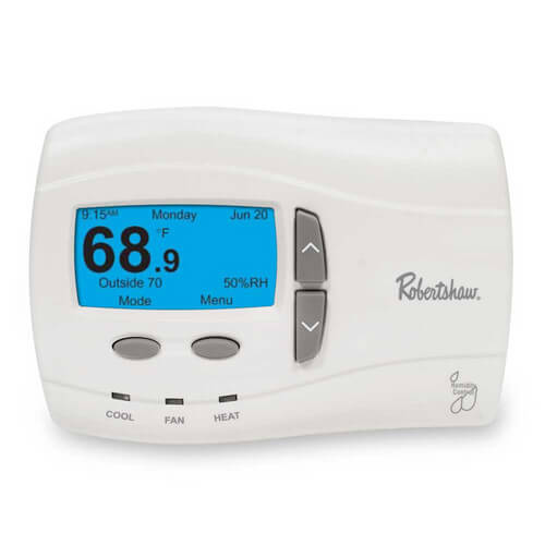
Robertshaw 9700 Manual
The 9700i thermostat was developed with the customer in mind. Finally, a programmable thermostat thats easy to program. Similar to a cell phone, this programming style is so easy, you dont even need a manual. I was looking for a new thermostat and found RobertShaw/Invensys 9700 Series thermostats. After reading the user manual, I realized that the.
Quick Start Installation Manual 111-304C Installation DOs and DON’Ts DO. Shut off all power to system before installing. Read entire manual before installing. Make sure that all wiring conforms to national and local codes. DO NOT.

Robertshaw 9700 Thermostat
Install on voltages greater than 30 VAC. Short jumper across terminals on the gas valve or at the system control. Connect ground to any terminal in this unit. Install on outside walls or in direct sunlight. Select location for installation. 1 To open battery door, slide it to the right. Open the case with a coin by placing it in the slot and gently prying forward at all three locations.
2 Mark mounting hole locations on wall. 3 Drill 3 / 16 ” holes at marked locations on wall. Insert plastic anchors into holes.
Covers models:Hatchback Corsavan plus Combo Van Including Special/Limited Editions 1997 –2000 Petrol motors covered:●1 litre (973 cc) DOHC “X 10 XE”3-cylinder ●1.2 litre (1196cc) SOHC “X 12 SZ”4-cylinder ●1.2 litre (1199cc) DOHC “X 12 XE”4-cylinder ●1 point 4 litre (1389cc) SOHC “X 14 SZ”4-cylinder ●1 point 4 litre (1389cc) SOHC “C 14 SE”4-cylinder (multi-point gas injection) ●1 point 4 litre (1389cc) DOHC “X 14 XE”4-cylinder ●1.6 litre (1598cc) DOHC “X 16 XE”4-cylinder Does NOT cover Diesel models. Holden barina sedan.
Robertshaw 9700 Thermostat Manual
4 Align unit base over plastic anchors embedded in wall and secure with the screws provided. 5 Connect wiring between unit and furnace.
For Model 9700i (1H/1C gas/electric heating and cooling applications). 6 Cut out opening a b 1/4' 1-1/2' 1' Mark mounting hole locations on wall using unit base as template. Drill 3/16 holes a b Press anchors into holes until flush. Rc W Y Rh O B G G Y W R Thermostat Rh - 24VAC Rc - 24VAC W - 1st stage heating O - Not used B - Not used G - Fan Y - 1st stage cooling TERMINAL DESIGNATIONS 9700 i Equipment wiring terminals.
Please refer to furnace installation manual for proper connections. HP J1 FN Remove factory installed jumper if two transformers are used. Factory installed jumper DELUXE PROGRAMMABLE THERMOSTAT 9700 i Remove 1/4” of insulation from end of each wire 2 1 3.